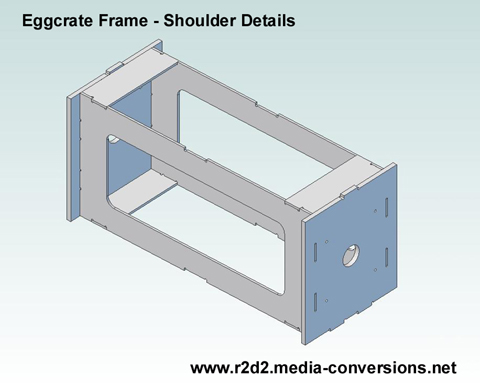
The Eggcrate Frame

The frame is one logical place to start building a driod so that's where my efforts started.

I wanted to be able to cut mine on a cnc controlled router. Why? As I mentioned in the background notes, I've already managed to cut a finger while using a knife and ruler to cut a piece of cardboard. As I read  R2 construction blogs, I ran across other builders who have has similar mishaps. I also wear glasses for reading and would find it hard to make repeatable accurate cuts. While that can be 'fixed' by sanding I'd rather not spend my time that way.

I also wanted to be able to 'tweak' the design. I wanted a droid where a rear panel could be lifted off for access to the inside (hinged was not necessary). That would mean cutting the support rings in the back which, without design changes, would weaken the frame. I've looked at Dave Everett's Styrene droid plans, but rather than trying to adapt them to cnc, I started over with the R2 Builder's Club "Body Flat Layout Drawing" to determine where to place the rings and ribs that would make up the frame. My modified version of that drawing is posted on the R2BC website. I can't post it here as it's a club drawing.

Since I was cutting my parts on a cnc router, I wasn't restricted by the requirements of being able to score and snap parts. So instead, I decided to use what I'm calling an 'eggcrate' design to tie the ribs and rings together. The name is taken from the interlocking cardboard dividers that are used to keep eggs, bottles, and other fragile items, from bouncing around inside a box. Instead of using score lines to determine parts alignment for the remaining parts I added tabs and slots to the design.  That also allows me to make non-symmetric parts only fir the 'right' way. The mounting holes in the shoulder plates, for example, are not symmetric. The plates can only be installed 'right side up'. For an example, and to understand what the consequences of using a design like that are, see my page on Eggcrate and Tab & Slot Design. I believe the combination makes for a stronger design. I also have the option of cutting parts thicker than the 3mm/.125 thickness that Dave Everett used in his design. My drawings will call out .25 thick parts (for the shoulder mounting plates, for example) instead of two .125 pieces glued together.

So, what does the design look like? Let's start with the shoulders

Basically I built a box beam that links the two shoulder plates together.
The cross brace pieces are set back from the edges because otherwise they would interfere with the ribs. There are two notches in the middle of the cross braces. They are there to provide a mounting place for a center plate used to support, for example, slip rings to connect to dome mounted electronics.

The image links to a 3d pdf file, click on it if you want to be able to rotate the image around and examine it from other angles. (Note, the 3d.pdf file opens in a new window. If you have problems with the 3d feature you may have to upgrade to the latest version of Adobe Reader).

And here's the frame itself with the shoulder assembly in place.

Some of the ribs have been left out of this image so that you can see how the frame fits together. The eggcrate makes the frame almost completely self aligning.Just remember to put the shoulder assembly in place before you glue the top ring on!
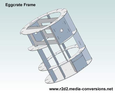
There are 5 rings (numbered 0 to 5) to the frame. Ring 0 is actually the skirt bottom. For now the frame is using two copies of Ring 1 for the bottom. Rings 2 and 4 are continuous. Ring 3 is actually in 4 pieces. Ring 3a fits between the front vents. Since it's alignment with the skins can be difficult it is not slotted. Ring 3b fits above the coin slots. Ring 3c, the largest segment, wraps around the sides and back of the droid. Ring 3d fits below the utility arms.

There are 5 different ribs to the frame. See the ring2 drawing for notes where each of the ribs go. The rib lettering corresponds to notes on the modified
Body Flat Layout Drawing that I posted on the R2BC site. Ribs a and a-left go around the front vents. There is no Rib b. Ribs c and c-left go between the utility arms and the large front doors. The left versions of those ribs have the extra slot for Ring 3b. (one each, total 4 parts). Ribs d and e surround the shoulder plates and the ankle insets. (4 each, total 8 parts). Ribs f and g are the same, they are used on the back of the droid (4 parts). There is only a drawing for Rib g.

The image links to a 3d pdf file, click on it if you want to be able to rotate the image around and examine it from other angles. (Note, the 3d.pdf file opens in a new window. If you have problems with the 3d feature you may have to upgrade to the latest version of Adobe Reader).

Dave Everett has said several times that he would not publish anything other than the .pdf versions of his plans. He also does not want them published anywhere except on the R2BC web site. The plans belong to him and that's his right. That's another reason that I derived these plans directly from the skin drawings.

Do my plans look similar to Dave's ? Yes, of course they do but that's because they both have to support the same skins and all of the skin details are in the same places.

What's different? Most of my ribs are in slightly different places. Typically on the centerline between the edges for panel openings. My ribs are all aligned radially from the center of the rings. This shows up in two places. The spaces behind the large front doors are pie shaped as are the areas around the shoulder plates. My shoulder plates are narrower as a result (they only have to be 6.66 wide to hold the shoulder hubs). They are also set deeper into R2's body than Dave Everett's design. [See the Shoulder Hubs section] What I loose in strength from narrower shoulder plates I make up by having the box beam tying the two shoulder plates together. Where there are holes in my parts they have been converted to English measurements (eg. .25 inch holes in the shoulder plates for 1/4-20 bolts).

What's missing, at least in this first version? The back panel is still fixed. The rear door I spoke about will be in a future version. All of the nice mounting holes for hinges and Rockler bearings are not yet in place. There are no cutouts for any of the detail parts (like the coin slots, power couplings or octagon ports.) Those will be added as I verify the fit while building the first frame prototype.

The design drawings are available as both Autocad .dwg files and Adobe .pdf files download drawing files with the understanding that the drawings are copyright to Media-Conversions and are not to be used commercially. (That note also appears on each of the drawings). I've also put together a set of assembly instructions to help you put the frame together.
Don't want to cut your own? You can try this parts source.

Revisions: I've posted version 1 of the drawings. No significant changes. I've added a .125 hole, marking the front of the frame, to each of the rings. You can see it in the .pdf above. It's possible to assemble the frame with ring2 turned around. The ribs will fit but they won't be strictly vertical. Hopefully the hole will help with orientation. I've also added a set of holes in the ribs to identify which is which. One hole for rib a, 3 holes for rib c, and so on. All of the bolt holes have been made .125 inch. That way you have your choice. You can drill them out for english (1/4 inch) or metric (m6) or change the versions of the drawing you machine from and have your cnc cut them to size. The hole in the shoulder plates has been set to 1.2 inches (30mm) to match the hole in the shoulder hub drawings. Version 2 of the drawings is now posted. Updated ring 1 drawings to have clearance area for octagon ports.


Home