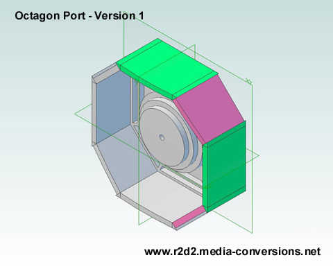
Click on the image for a 3D .pdf version.
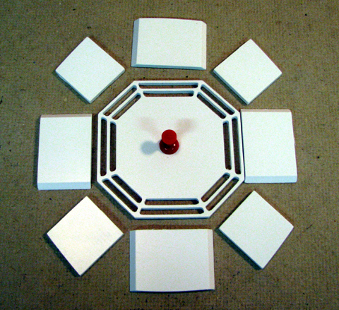
I cut a set of parts
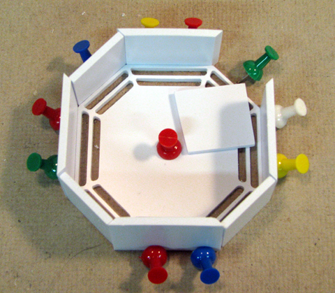
But I didn't anticipate how hard it would be to keep them in alignment. - Back to the Drawing Board!
|
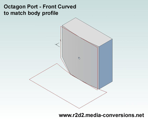
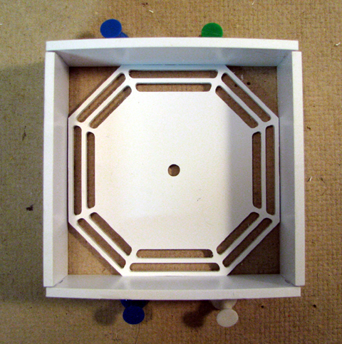
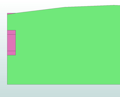
This was my
version 1 design. It was
derived directly from the R2BC drawings. I put the bevels on the
top/bottom and left/right pieces so that the 4 corner pieces are all
the same. Click on the image for a 3D .pdf version. |
I cut a set of parts |
But I didn't anticipate how hard it would be to keep them in alignment. - Back to the Drawing Board! |
 |
 |
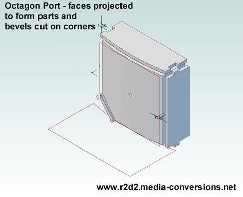 |
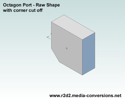
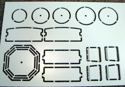
Each
face is projected onto a separate plane to create the top/bottom and
left/right sides of the box. The edges are extended at the corners and
tabs are inserted. I didn't bother putting fillets on the tab edges as
I did with the egg crate designs. The slot is cut oversize so that the
rounded edges of the tab have extra space. The cut corner is projected onto a parallel plane and then the bevels are cut on the edges. This has to be done twice, once for each corner. (Only one shown here). |
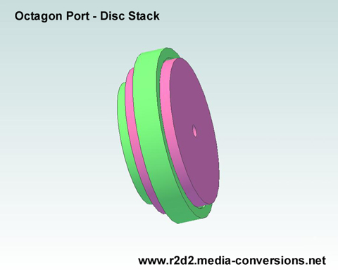 This is the stack of discs that make up the center of the port. Click on the image for a 3D .pdf version. Note the pocket cut into the bottom of the largest disc. |
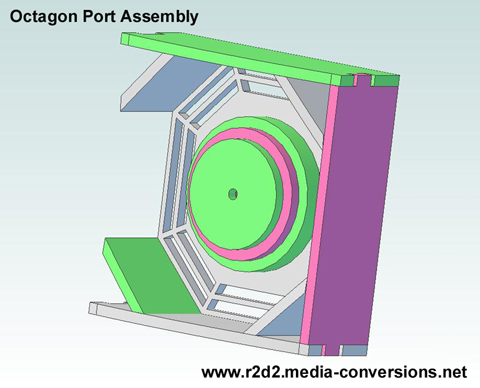 I've hidden the left side of the assembled port so you can see how the disc stack fits. Click on the image for a 3D .pdf version. |
 | 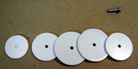 The stack of disks with an 8-32 screw for alignment |
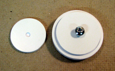 make sure the pocket is facing the bottom of the stack then clamp and glue | 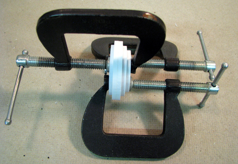 |
 | 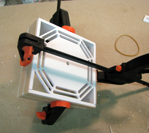 The tabs & slots with the rubber bands hold the box together. The clamps insure a tight joint. Apply glue just to the joints between the bottom and the sides. |
 Insert the corners and glue the remainder of the joints. | 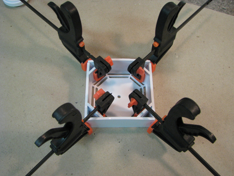 be careful how much force you use to clamp the corners It's not visible below, but I spread open one of the box edges which dosn't matter, since it's not visible when you mount the octagon port behind the skin. |
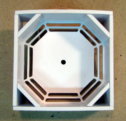
 That little sliver of pink box edge will have to be filed off by hand to get a smooth fit to the skin | 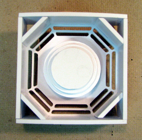 |
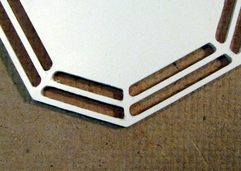 | Above: the disc stack in placed in for the photo. Paint first Left: The spider web slots are cut with a .0625 dia bit so they come out slightly rounded. A few minutes with a needle file sharpens up the outer corners. |
| Home |