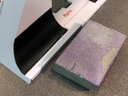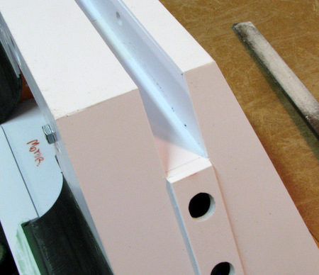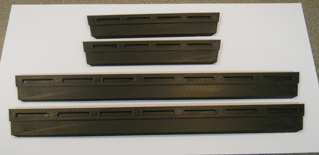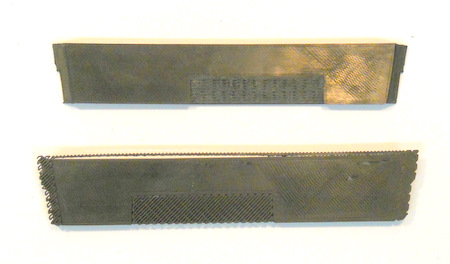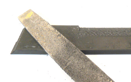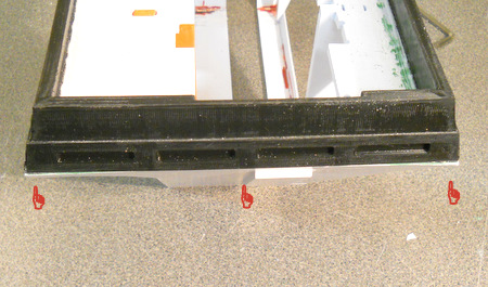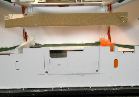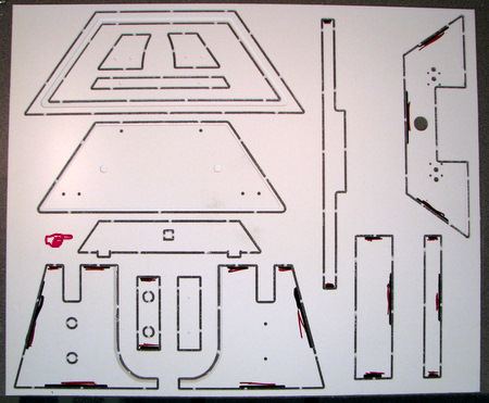
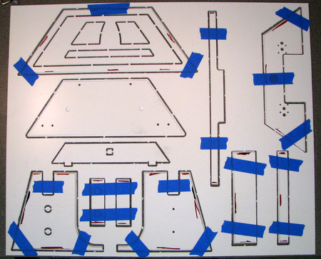
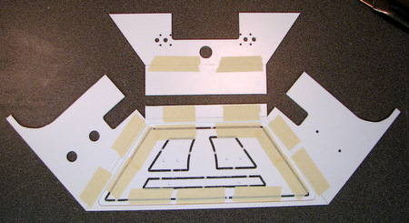
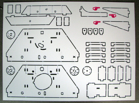
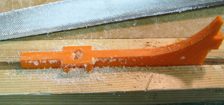
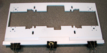
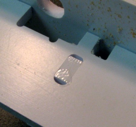
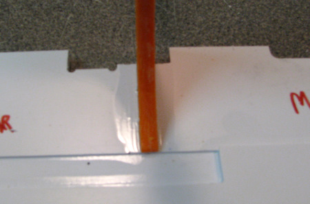
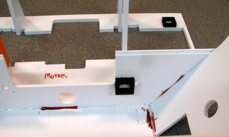
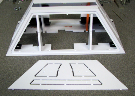
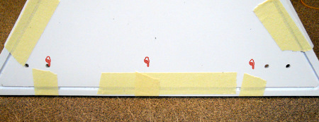
parts have been marked for cutting bevels
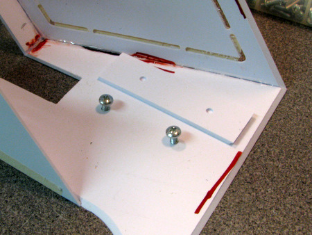
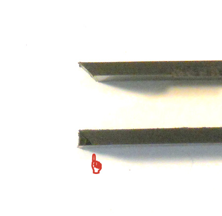
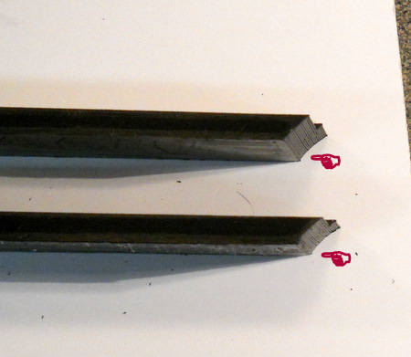
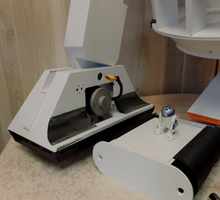
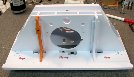
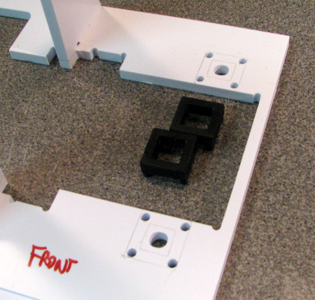
part noted in red is part of the drive assembly.
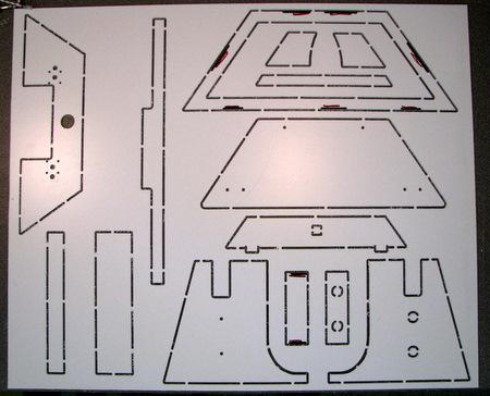
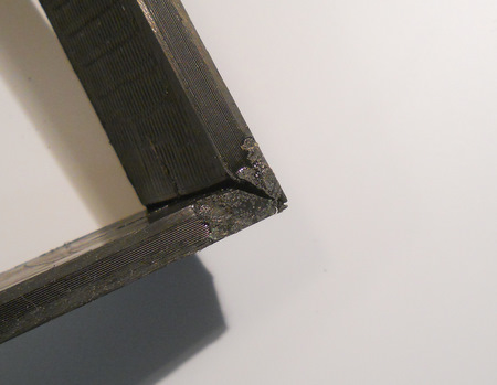
bevels are cut on the 'underside' of some of the parts which is one of the reasons they are cut on a router table.
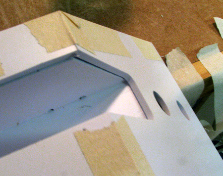
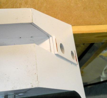
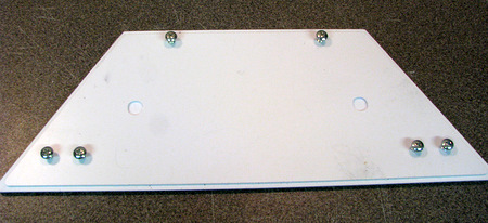
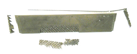
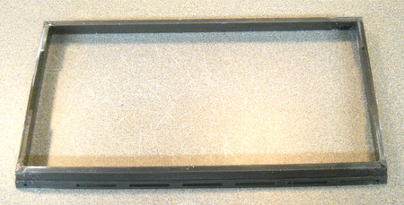
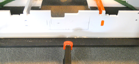
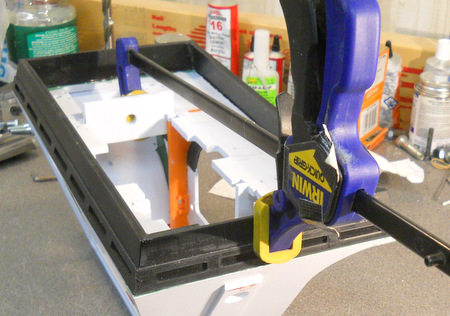
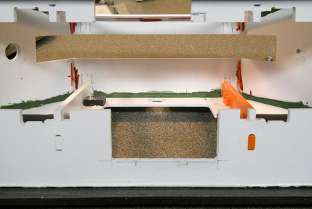
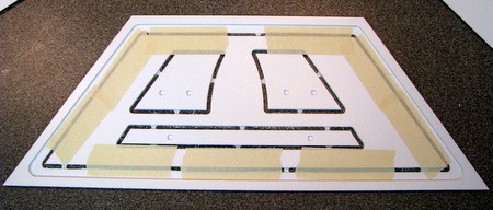
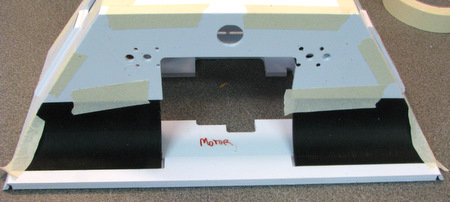
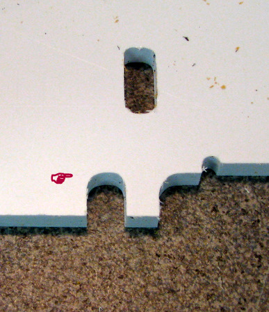
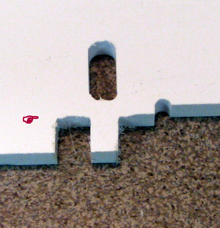
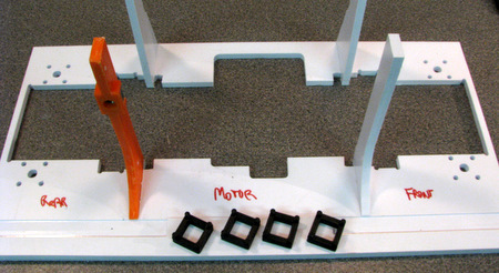
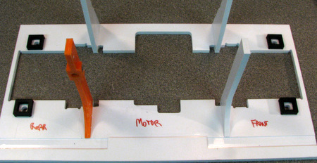
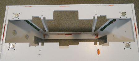
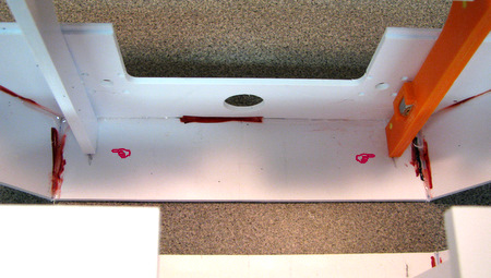
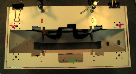
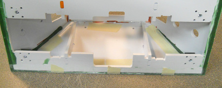
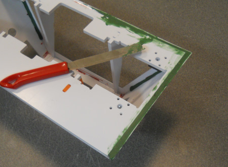
above: note that the parts inside of the side frame are left in place. this is to reinforce the frame during assembly.
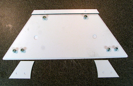
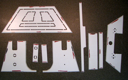
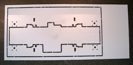
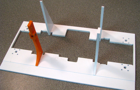
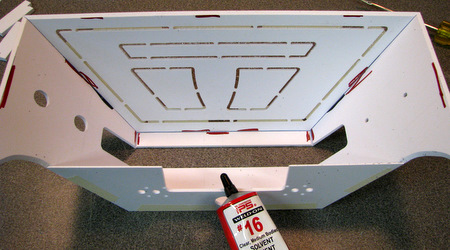
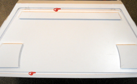
Right: lay the shell parts out with the bevels down
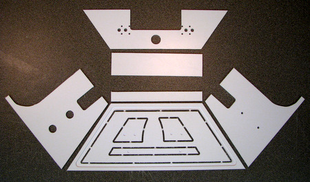
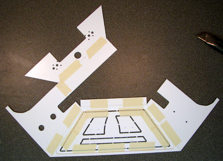
fold the remaining edges together and tape, making sure the corners line up
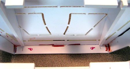
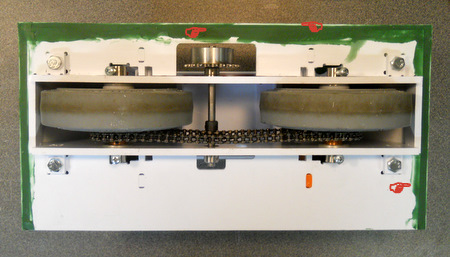
this is a view from the inside of the shell
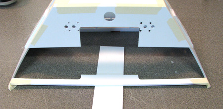
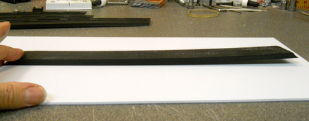
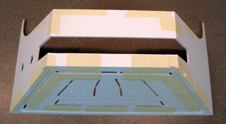
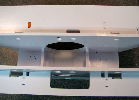
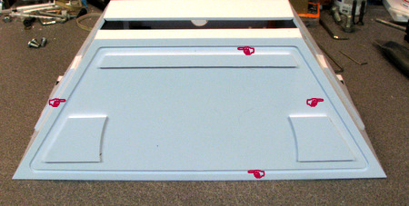
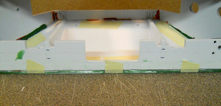
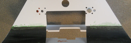
Above: tape the bottom filler strip to the ends of the two shell end plates. It will 'droop' a little, put a piece of scrap under it to keep it flat while you are taping it.
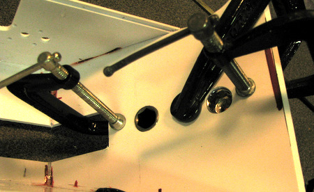
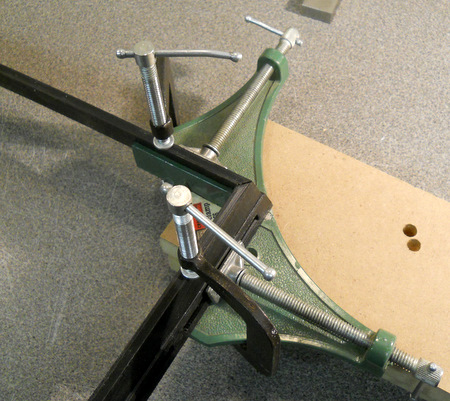
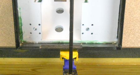
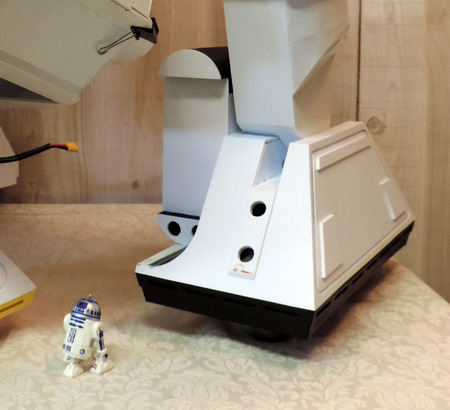
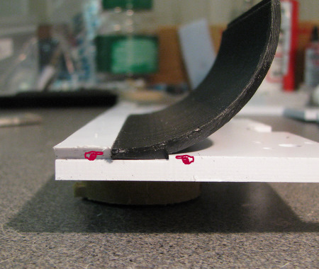
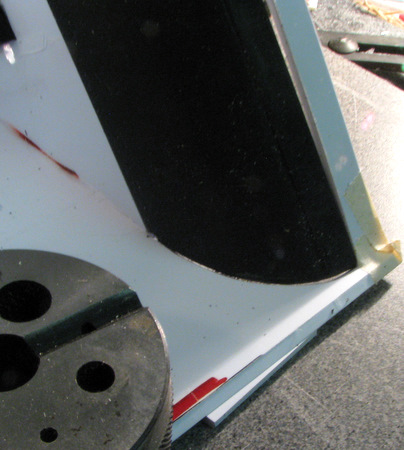
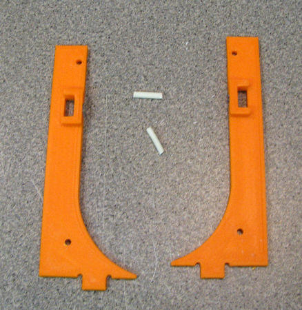
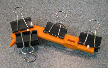
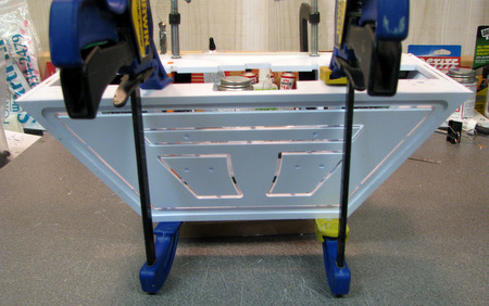
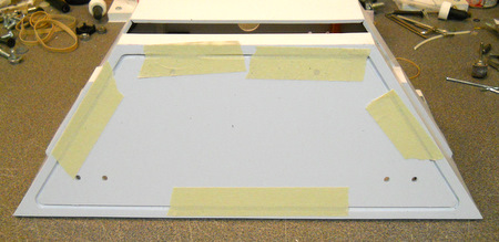
turn the shell on end, use a weight to help prop it up. place the curved end in position, using the lap joint on the top edge to hold it in place.
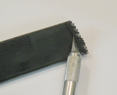
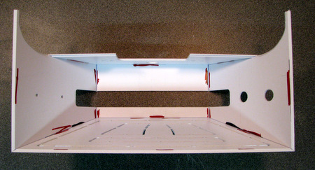
with a light behind the shell you can see where the gaps in the joint between the curved end and the shell end are. working slowly and carefully, file the profile of the curved end to eliminate the high spots.
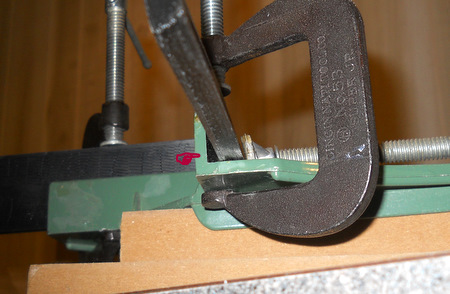
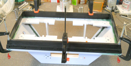
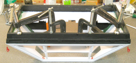
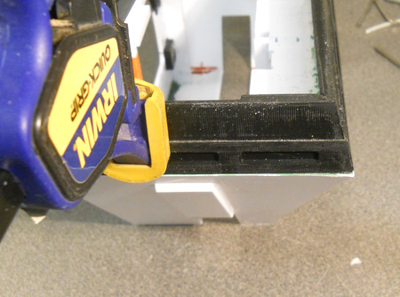
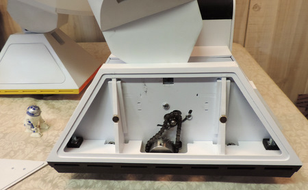
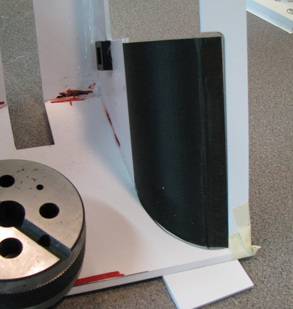
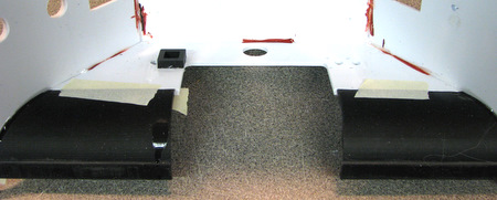
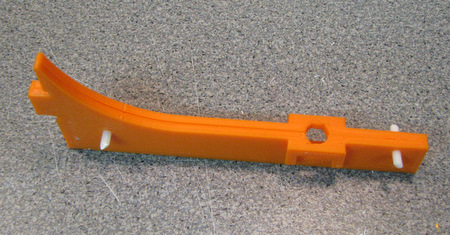
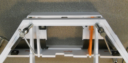
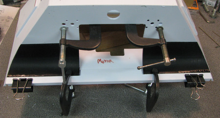
Above: With both ends adjusted for a good fit, put the shell on the brace and tape the curved end pieces to the rest of the shell. Tape the lap joint on the inside for extra support. Then remove the brace and (see below) glue the joints on the curved end pieces.
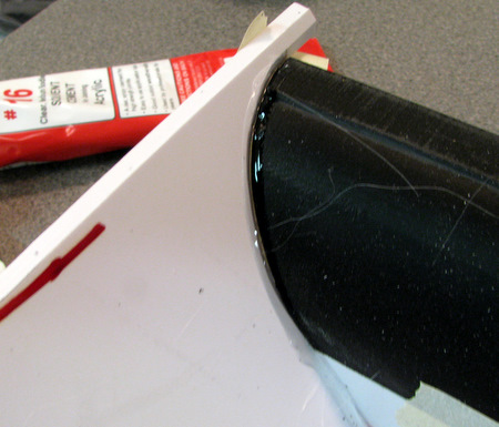
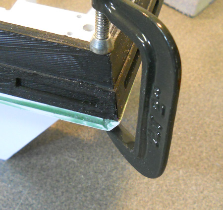
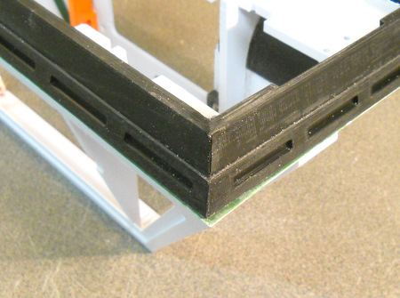
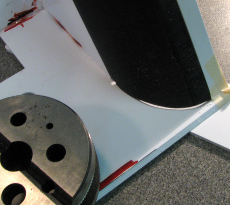
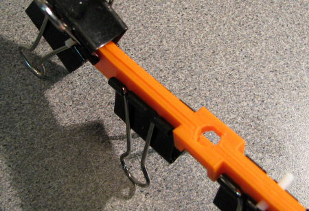
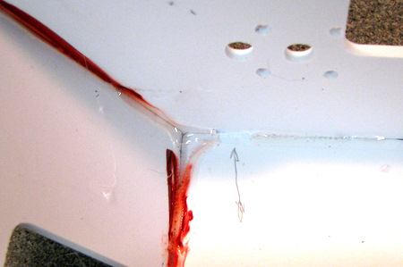
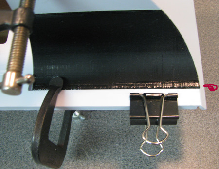
Above: note the use of tape on the inside of the lap joint to hold the curved ends in place while the glue sets. take the opportunity to put a few drops of Weldon #3 into the inside of the lap joint while the Weldon #16 on the curves is curing.
Don't use Weldon #16 yet. that will go on later!
 if you get
glue into the areas where the braces go just scrape
it out!
if you get
glue into the areas where the braces go just scrape
it out!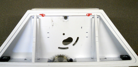
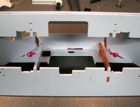
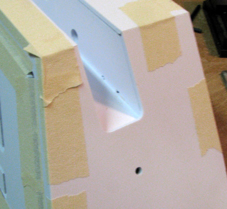
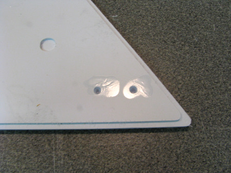
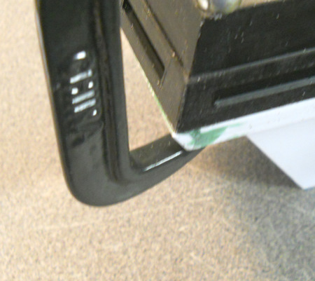
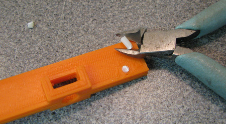
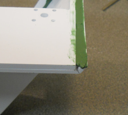
 Right: Once the
glue has dried file down any rough edges.
Right: Once the
glue has dried file down any rough edges.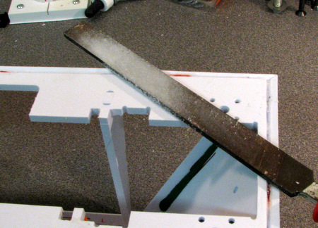
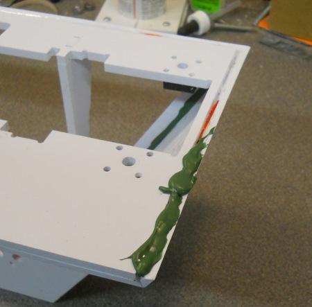
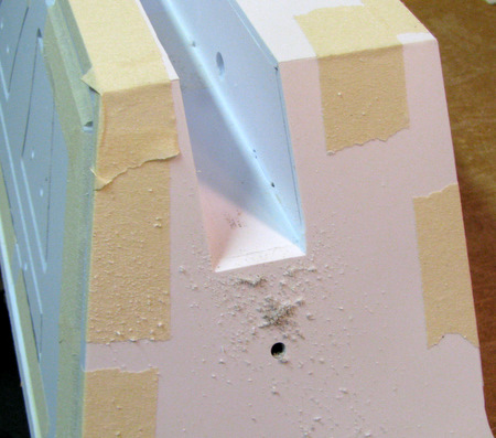
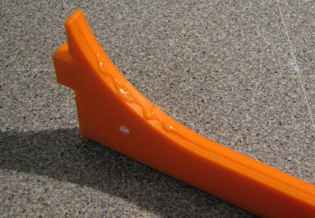
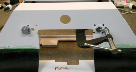
 Above: also
put
some putty on the curved end joints with the shell (remember the
battery box covers most of those joints.)
Above: also
put
some putty on the curved end joints with the shell (remember the
battery box covers most of those joints.)