The image links to a 3d pdf file, click on it if you want to be able to rotate the image around and examine it from other angles. (Note, the 3d.pdf file opens in a new window. If you have problems with the 3d feature you may have to upgrade to the latest version of Adobe Reader).
After 'activating' the 3d mode by clicking on the display
select a part by left clicking on it (the part will be highlighted)
then right clicking brings up a window. Follow the sequence
-> part options -> part render mode -> transparent
to make the outer parts transparent and the inner
details visible.
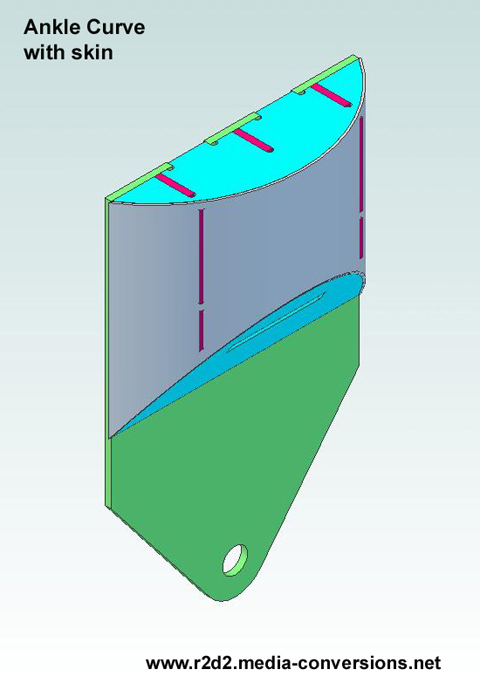
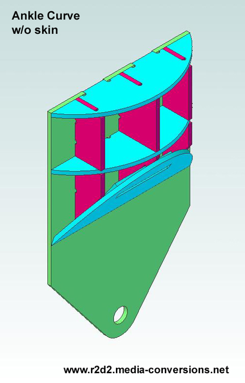
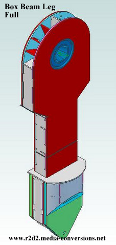
Or you can use the views below which also link to .pdf files.
 this
version has the back removed to show
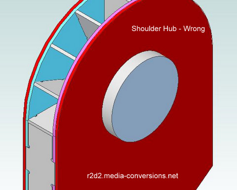
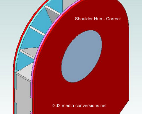
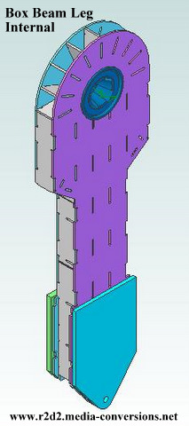
this
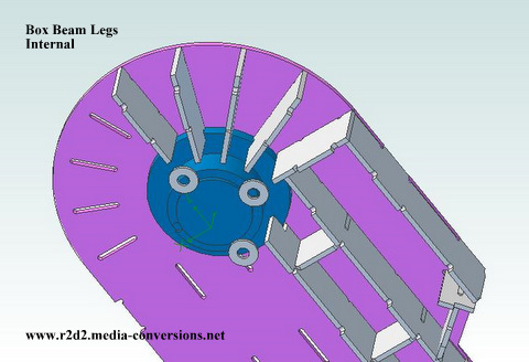
version has the back removed to show the Shoulder Hub Mounting Details
Note: Shoulder Hub not included with the Parts Package