The 3D Printed Battery Box Assembly

Standard & with Cutout

There are two different versions of the 3D Printed Battery Box. The "3D Printed Battery Box" is complete on all surfaces and differers from the R2BC spec in that it has two bolts on the end opposite the hose connections that allow you to take it apart. The "3D Printed Battery Box with Cutout" has been modified to accommodate the scooter motor of the outer foot drive. The Motor extends into the Battery Box. In addition it has holes for mounting it to the outer foot shell and an internal shelf to hold a battery and mount an ESC onto. Both boxes have components in common and they are assembled in the same way. The instructions immediately below are for the "standard" battery box. After those instructions are assembly instructions for the battery box with Cutout. I'm only providing instructions, for the "with Cutout" box where there are significant departures from the standard assembly. Make sure you review the standard assembly instructions First!

First step is to separate all of the parts from the sheets they were machined from, remove the tabs and flash, if any

These are the parts needed for 1 battery box. You should have 2 sets since they come in pairs. [2 corner fillers are shown - there will be only 1 for each battery box]

During the prototype process I decided to replace the more complicated door bottom and frame (top pieces) with a single piece door bottom.
The 3D printed parts shown here were printed using Black ABS filament. Since the printed parts have to be primed and painted (just like any of the other parts on R2) there's no apparent advantage to one color over another. In the future, I'm most likely going to print all of my parts in either White ABS or what's called Natural ABS (a Milky White color). Considering that I have a stock of Black ABS and Silver ABS to use up, there are no guarantees on which color you might receive.

I used a tapered reamer to enlarge/smooth the holes.

The front door panel can be identified by the longer lip

This set of curved ends has a ridge running along the edge.

Take a moment now to sand it down.

Above: Fold over a piece of sandpaper and run it thru the channel in the curved ends.
Right: Once the sandpaper slides easily I put a doubled over envelope in between to open up the channel even more.

also sand the channel in the center piece that the edge of the door panel seats into.

Dry fit the parts to make sure they fit together easily. You should be able to slide the front door panels easily in the channels of the curved ends. You can also sand the edges of the door panel to make sure they are smooth.
Below: also check the fit of the rear door panel with the center piece

Right: now is a good time to cement the two 1/4-20 square nuts in place. While that's silicone cement in the picture I found I got better results using E6000


Next steps will be to glue the parts together.

I 
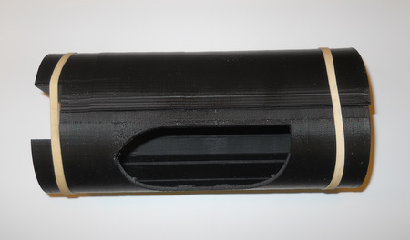
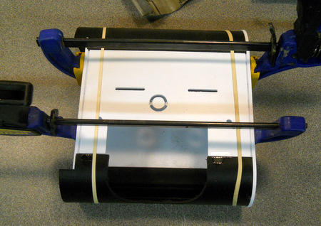
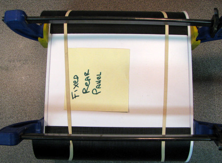
used a pair of heavy duty rubber bands to hold the curved ends while I clamped the center piece and the rear panel tightly. Bolt the bottom in place to secure the curved ends. Then put a few drops of Weldon #3 on the joints between the rear panel , each curved end and the center piece

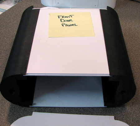
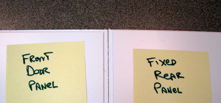
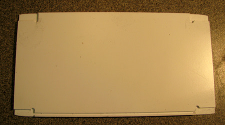
Once the glue has cured, remove the clamps and unbolt 
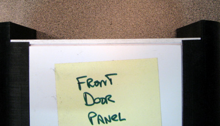
the bottom. Then carefully slide out the front door panel.

I 
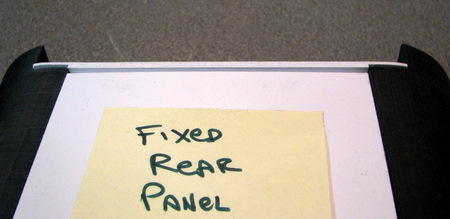
put rubber bands back in place to avoid over stressing the joints. Now put a bead of Weldon #16 on the inside joints of the curved ends and the back panel. let the glue dry.
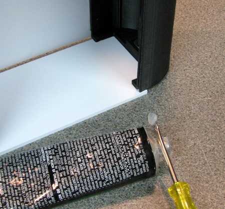
Turn the assembly on it's end and put a bead of Weldon #16 around the 
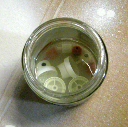
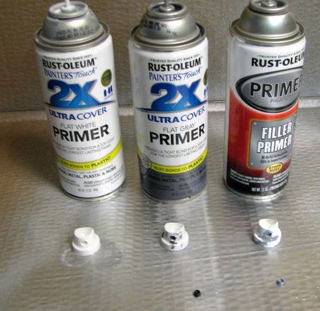
joints. Because of the tight quarters, I found it easier to use a 1.5oz tube of cement instead of the larger 5oz tube I usually use.
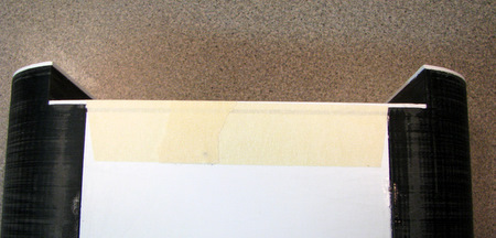
once the rear panel joints are dry check the front door fit again. It should 
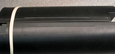
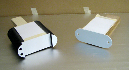
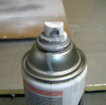
still slide smoothly. put some tape over the ends as shown.

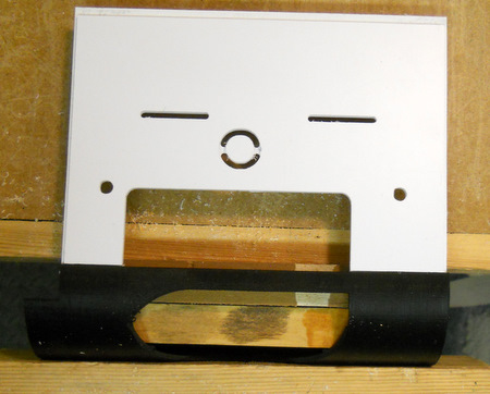
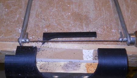
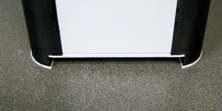
bolt the bottom panel in place. The countersinks establish the location of the panel.

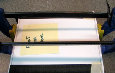
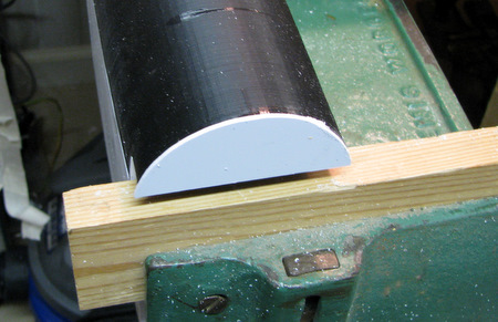
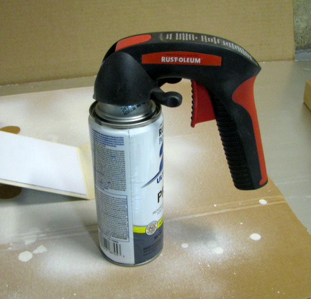
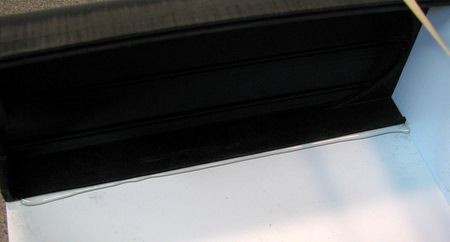
Above: Clamp. This time we want the clamp force in the middle of the joint.

Right: Put just 2-3 drops of Weldon #3 in the middle of the joint. You want to be careful to NOT glue the bottom panel to the curved ends. [That's what the tape is for!]
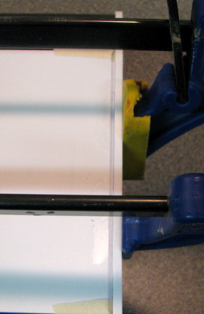
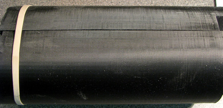
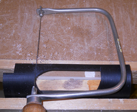
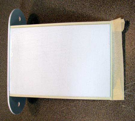
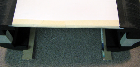
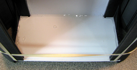
Below: when the glue is dry, unclamp and unbolt. then peel the tape back. To avoid stressing the joint, push the door down from the top. then remove entirely. handle carefully as there is very little area in the glue joint.
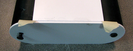
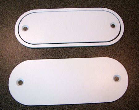
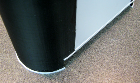
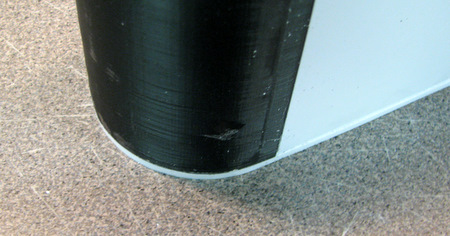
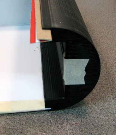
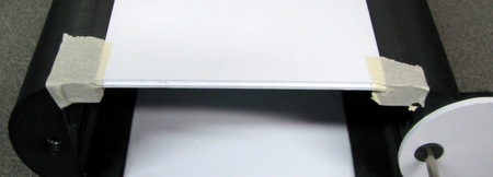
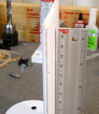
Right: as you can expect, the resulting joint comes out square.That's not what we really want since that joint, and the bolts, are all that hold the back door tightly against the back of the battery box.


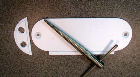
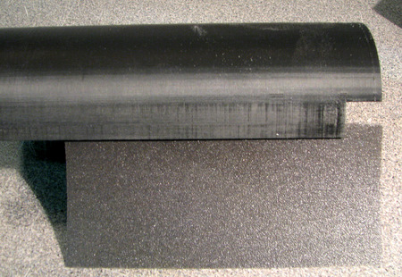
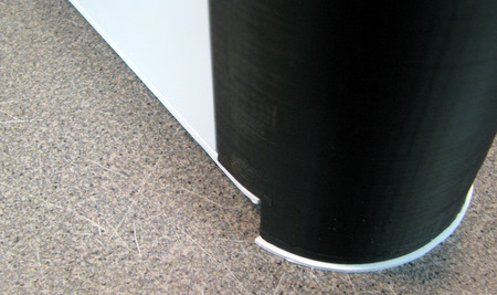
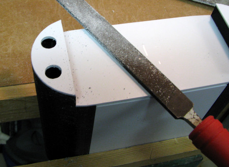
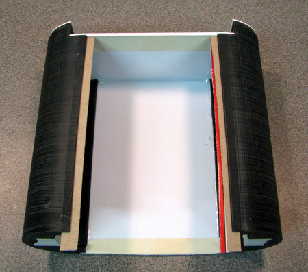
Left: before we proceed to reinforce the joint, very carefully bend the door so it's at a slight angle to the end.
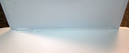
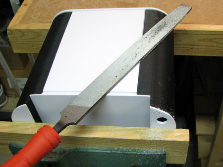
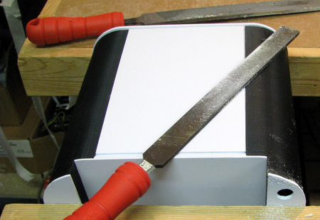
Above: then run a bead of Weldon #16 on the inside of the joint.

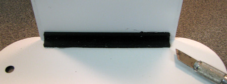
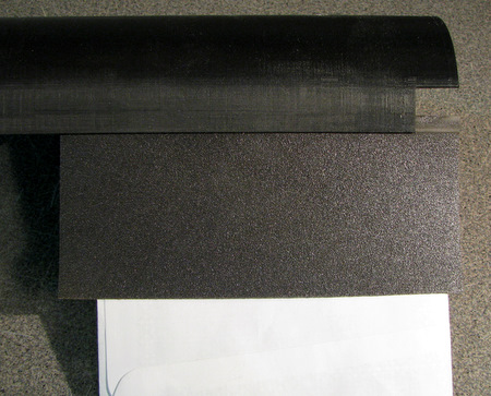
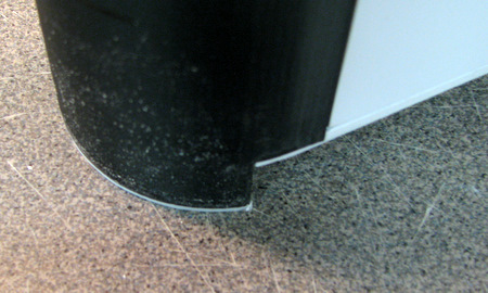
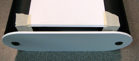
Above: before the glue sets press the corner filler into place. use the blade of an X-Acto knife to remove any glue that might squeeze out of the ends and block the fit of the door. Keep the slight angle in the door when you press the corner filler in place.

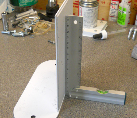
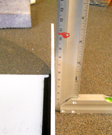
Right: Slight angle after gluing. This time measured at the end.
while you are waiting for the door panel to dry glue the two end pieces in place. wipe off any excess glue. place the box upside down to hold the parts in place while the glue dries.

Remember that the end pieces determine where the hose connections are and therefore if you have a right or a left battery box. Make sure they match what you need and you make two different ones!


Now that the all the parts are glued in place we'll file the edges.Take your time with this step. I tend to use a coarse file because it does not get clogged easily but it also removes plastic quickly. It's easy to remove too much!

most of the edge parts are about .040 oversize so that they can be trimmed to fit.

The center piece, where the front door panel fits is the exception. It's cut to size. The slot (for the door panel) makes it more fragile so there should be minimal filing.

I clamp my battery box in a bench vise. Just don't clamp down too hard.

Left: I start with a rather coarse file. It removes material quickly.
Above: I switch to a finer file as the edge gets  close to finished. Remember to hold the file square to the edge.

Above: shift the battery box around when it's time to do the edges on the curved end
Right: I'm right handed, so when I need to do the inside edge I make sure it's on my left.

Be careful when clamping this way so you don't crush the battery box.
</big>
Above & Right: here's what finished edges look like


These are the instructions for the "3D Printed Battery Box - with Cutout". I'm only providing instructions where there are significant departures from the standard assembly. Make sure you review the standard assembly First! With the "standard" battery box you got two sets of identical parts. The only thing that determined if you had left or right battery box was the position of the piece with the holes for the hose mounts. Now you also have a curved end with a hole in it and the fixed rear panel has a matching cutout so be careful to separate the sets and not mix up the construction.
 The position of the cutout determines where the  "back" of the battery box (the side that mounts to the outer foot) is located.
The curved pieces with cutouts, and the matching back panel with cutouts, come as mirror-image parts.

shown here being dry fit and clamped in a vise. note the 2 blocks on the inside of the curved part. do not tighten the vise down hard!

cut away the support piece that bridges the gap. I'm using a coping saw, but a regular hacksaw would work as well.
Below: file any roughness off the cut edges

Right: from this point, assembly continues just like the "standard" battery box. Note: when it comes time to glue in the two curved end pieces make sure the one with the hose connection holes goes in the correct place.

Next step is painting. I'm just learning how to finish paint R2's plastic parts. I've painted lots of things over the years but this is my first foray into finishing either HIPS or ABS versions of Styrene. The battery box is noticeably cleaner in the photo's that follow. In addition to being vacuumed, it was washed in hot water and then dried overnight.

Apply tape to the door panel edges They are hidden and the slots they slide in are already tight.

I put doubled over pieces of cardboard (cereal box, scored and folded) to keep paint from going into the slots. Remember to remove the cardboard after spraying, before the paint sets!
Left: cover over the square nuts.


Above: In this first pass at painting we're going to be priming the curved pieces. I expect they might need multiple coats. I'm covering over the rear panel edge to avoid paint buildup.

Above: the same applies to the top edge of the rear panel. you want to avoid filling the panel detail with paint.

Right: I'm going to be trying out 3 primers. The Gray primer for the white parts, the white primer over one black curved end and the filler primer over the other curved end.
Below: part of the preparation is to set up a place for the painted pieces to dry  without being disturbed. Here I'm using  blocks of wood that are high enough to keep the painted surfaces from touching.
Right: The Rust-Oleum instructions say to use mineral spirits to clean the spray can nozzles. After a previous painting session I put my spray paint nozzles into a small jar of mineral spirits figuring that would keep them clean. As you'll see, I don't think it worked
NOTE: Rust-Oleum Customer Support indicates that you should limit the amount of time you leave the nozzles in the mineral spirits to 20-30 min. Based on my experience I'm going to continue to use the bottle of mineral spirits for Cleaning (eg, drop a nozzle in, shake, remove) but not Storage.

The instructions also say to shake the cans for a full minute. Put a clock, with a minute hand, where you can see it. I tend to cheat if I don't use a clock!

There's not much to paint in this session, but a clip on handle makes spraying a lot easier. Otherwise your 'trigger' finger gets tired!

So, when I started spraying this is what happened. There's part of the spray nozzle missing here, paint leaking out all over and spattering on the piece being painted!

The same thing happened to each of the 3 spray nozzles that I tried using. I was able to find 2 out of the 3 missing pieces. The last one is somewhere in a corner of my garage. Doesn't matter as they won't stay in place in the nozzle.

Please send me comments, questions, or suggestions on making the design better to me at: fpirz (at) media (dash) conversions (dot) net


Home